A history of the APAS docking systemby Maks Skiendzielewski
|
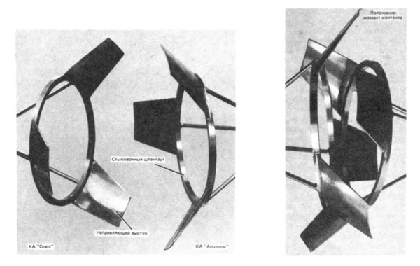
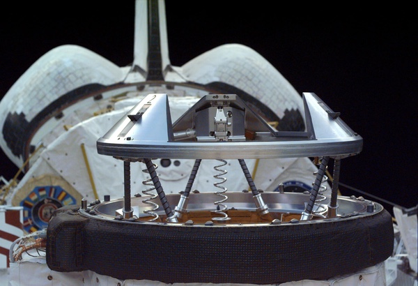
| APAS-89 is a fully androgynous docking system, with both the chasing and target spacecraft carrying an identical assembly and either able to assume the active role in the docking process. |
A year after the success of the Apollo-Soyuz mission, V.S. Syromyatnikov’s team at NPO Energia’s robotics division started preliminary work on a prospective successor to the APAS-75 system that would fully embrace the idea of androgyny and use a single docking port design capable of docking to itself.
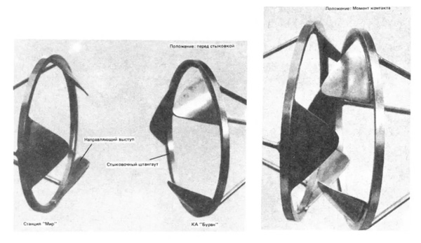
Now with the full support of NPO Energia’s chief designer Valentin Glushko, the new APAS was developed to provide the basis for a unified series of derivative variants for special use cases and quickly became the default docking port for NPO Energia projects, being included in the plans for Buran, the Mir-2 space station in all its iterations, and the various spacecraft projects such as the reusable Zarya capsule.[3]
Alongside the baseline fully androgynous version, the port could be configured as exclusively passive; as a soft-dock-only version (without the hard-docking collar, e.g. for EVA servicing missions of satellites); or as an unpressurised version with the hard-docking collar.
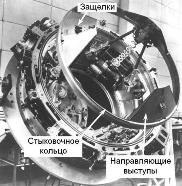
 Simplified model of the new APAS interface. (credit: Zemlya i Vselennaya, №3 1992) |
The new system would keep its predecessor’s three-fold rotational symmetry for the capture mechanism, but the petals on the capture ring would now be canted inwards instead of outwards. This had the major benefit of freeing up the perimeter of the docking port for sensor hardware, electrical, and hydraulic connectors, which would allow for the transfer of propellant between docked spacecraft. Another advantage of the inward-canted capture ring petals was that after a pressurized passage between two spacecraft was established, the cosmonauts were able to remove the capture mechanism from inside the pressurized volume to increase the passage diameter from 0.8 to 1.25 meters.
It was designed to have similar overall dimensions to the older SSVP system, which meant that it could be incorporated into the existing spacecraft designs without major structural changes. A later development was the ability to configure the docking port with the “probe-and-cone” capture mechanism from SSVP, while keeping the larger and stiffer hard docking collar from the new APAS.
 The first APAS-89 unit on display at the 1989 Paris Air Show. (credit: Keldysh Research Center) |
At the 1989 Paris Air Show at Le Bourget, the new design was presented to the public for the first time and received a name: APAS-89.[4]
APAS-89: a technical rundown
Before we get into the weeds, here is a quick refresher on the APAS-89 docking system. In its standard form, APAS-89 is a fully androgynous docking system, with both the chasing and target spacecraft carrying an identical assembly and either able to assume the active role in the docking process. The docking unit is 676 millimeters tall, of which 250 millimeters is recessed into the spacecraft’s hull and 232 millimeters represents the visible hard docking collar enclosure, with an outer diameter (excluding sensors and connectors) of 1,552 millimeters. With the soft capture ring in place, the internal passage diameter is 800 millimeters.
Each APAS-89 unit has a mass of approximately 300 kilograms, 120 kilograms more than the SSVP-G system in use on the Soyuz and 60 kilograms more than APAS-75.
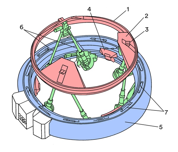 Simplified diagram of an APAS-type docking assembly. (credit: Patent RU 2 131 829 C1, modified by the author) |
To dock using APAS-89, the “chasing” active spacecraft extends the soft capture ring (1) to the “ready to dock” position; three rough alignment petals (2) are attached evenly around its circumference.
When the active craft approaches the “target” passive docking assembly, the identical set of rough alignment petals on the retracted passive mechanism guides the two soft capture rings together until the soft capture latches (3) on the active craft engage the strikers (4) affixed to the hard docking collar (5) of the passive mechanism. When capture (or “soft-docking”) has been achieved, the six mutually connected ball screw rods (6) and dampers absorb the docking force and dampen the resulting oscillations.
Then, the capture ring is fully extended to align the two docking units in preparation for hard docking. The capture ring then fully retracts until the two hard docking collars make contact. To complete the docking procedure, active hooks on hard docking latches (7) engage passive hooks on the opposite hard docking collar, sealing the two collars against each other and forming a hermetically sealed passage between the two craft.
To undock, the hard docking latches are released by the active spacecraft and two undocking springs on each docking unit push the docking ports away.[5]
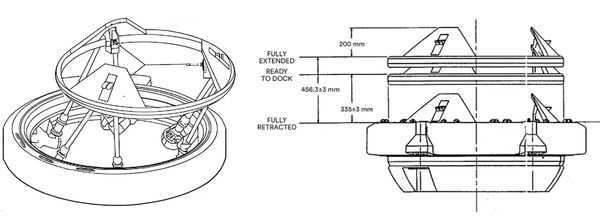 Left: Illustration of the maximum lateral displacement of the capture ring. Right: Drawing of the three extension positions of the soft capture ring (credit: capcomespace.net, JSC-26938, modified by the author) |
The soft capture mechanism was described elegantly in a later document:
[The mechanism] provides capability to extend and retract the guide ring as well as attenuate mating loads while the guide ring is in the initial [“ready to dock”] position. The mechanism consists of a guide ring supported by three sets (six total) of ball screws which in turn are supported on the base assembly. The ball screws are attached by universal joints on each end. Adjacent ball screw sets are interconnected by means of a gearing between the universal joints. One screw in each set has a left hand helix thread with the other screw having a right hand helix to provide translational capability. The three output shafts of the ball screw sets are summed through three interconnected differentials into a single output which drives a spring assembly, friction brake (attenuator), and gearbox/motor/brake assembly. Three electronically operated locks (fixers) hold the ball screws in a synchronized condition during extend and retract. The ring is driven with an actuator that consists of redundant motors driving the output through a reduction unit. [6]
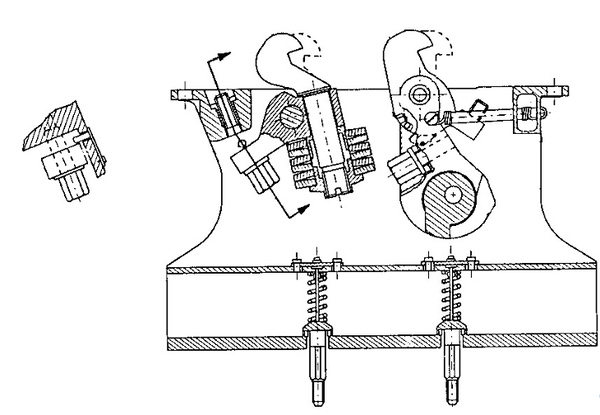
Twelve hard docking latches are located on the hard docking ring. Each latch contains a pair of structural hooks; one active and one passive. The active hooks are actuated in two groups of six, comprising of alternating latches around the hard docking ring. When docking, the chasing spacecraft actuates the active structural hooks of the first group against the corresponding passive hooks on the target spacecraft, then actuates the remaining six hooks of the second group.
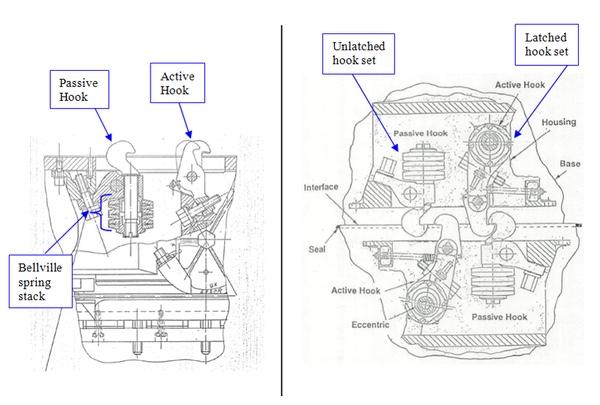 The hook assembly of an APAS-89-type assembly. (credit: Kerry Ferrand's archives) |
If the active hooks of the chasing spacecraft fail to engage, the target spacecraft can use its own active hooks of the same group to complete the docking. Both the active and passive hooks could be fitted with explosive bolts to undock the spacecraft in case the hooks failed to retract, though before Space Shuttle flights to Mir that option was not exercised, with the axial APAS-89 assembly on Mir’s Kristall module only fitted with explosive bolts for the twelve active hooks.[7, 8]
 Explosive bolts on the passive (left) and active (right) hooks of an APAS-89-type assembly. (credit: Kerry Ferrand's archives) |
Between the latches on the hard docking ring, two alignment pins and corresponding holes are located, as well as two undocking springs, two “undock complete” sensors, three “interface sealed” sensors and three “ready to hook” sensors. On the periphery of the hard docking collar, two pairs of interface connectors with 154 and 180 contacts are placed. On one side, the two structural hook actuator covers are visible, with the external mechanism connector panel between them. An additional set of four hydraulic connectors was available, arranged in a square on the periphery of the hard docking collar, which enabled the transfer of propellants between the docked spacecraft.[9]
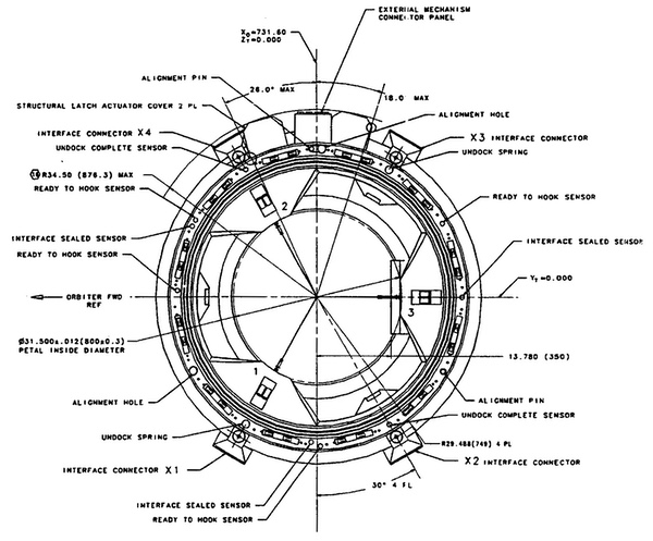 Diagram of the interfaces on an active APAS-89-type assembly. (credit: JSC-26938) |
APAS-89 and a slow start
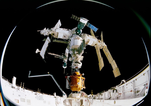
The first two APAS-89 assemblies to travel to space were installed on the Mir station’s Kristall module: the axial port would receive Buran orbiters, while the radial port would be used to berth research modules of the 37K series carried in Buran’s payload bay. The APAS units on Kristall did not have the two circular rubber gaskets on the hard docking collar, relying on the set mounted on the visiting spacecraft to achieve a hermetic seal. Only the twelve active structural hooks were fitted with explosive bolts to release the latches in an emergency.[10]
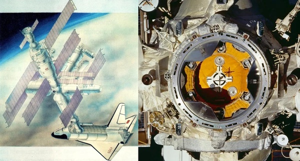 Left: Buran docked to Mir’s Kristall module. Right: Kristall’s axial APAS-89 docking assembly. (credit: RKK Energia, NASA) |
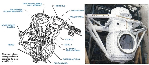
Speaking of Buran, for missions to Mir the orbiter would be equipped with the Docking Module, which contained an airlock and an APAS-89 docking port. In the end, no Buran orbiter ever visited Mir, but a docking with the station was scheduled for the cancelled second mission of the program; to be flown by orbiter 2K.[11]
Soyuz spacecraft equipped with APAS-89 would serve as rescue vehicles for Buran in case the orbiter was stranded in orbit away from the safe haven of Mir. Three Soyuz-TM-series spacecraft were ordered for this purpose, serials 101, 102, and 103, though only 101 was actually built; it ended up flying to Mir in 1993.[12, 13]
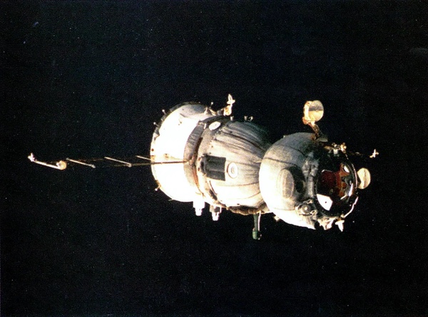 APAS-89-equipped Soyuz TM-16, originally built as the first Buran rescue Soyuz, serial TM-101. (credit: ESA) |
In all three of those applications, the APAS-89 units were the fully androgynous variant—the docking system could assume both the active and passive role as required. As Kristall would only receive spacecraft, it would effectively only operate as a passive port (with the capture ring retracted), but it did include the complete soft-capture mechanism and could assume the active role. In fact, during the Shuttle-Mir flights, one of the contingency plans if some of the orbiter-side hard-docking hooks failed to engage had the Kristall-side active hooks actuate instead to complete the seal. [9, 14]
The APAS-89 assemblies on Kristall had the NPO Energia part number ending in 008–01—it’s a surprise tool that will help us later. [15, 16]
STS-71 and the first shuttle to dock to Mir
In June 1992, the US and Russia decided to collaborate on an international spaceflight project, announced as the International Space Station program in September of that year. In Phase One, both countries would exchange seats on their spacecraft and the shuttle would fly missions to Mir, followed by the construction of a new International Space Station in Phase Two.
| While the use of the existing APAS port on Kristall was an easy choice, given its Buran-related origin, the shuttle side was more complicated. |
Flying foreign crew on the Space Shuttle and Soyuz did not pose a serious technical challenge (although it did lead to a loosening of crew height restrictions on the Soyuz for the later TMA variant), but the shuttle missions to Mir required—déjà vu—a docking of two technologically unrelated spacecraft. In 1992, Rockwell, the shuttle orbiter’s prime contractor, entered talks with NPO Energia to jointly develop a docking system for Shuttle-Mir. [17, 18]
While the use of the existing APAS port on Kristall was an easy choice, given its Buran-related origin, the shuttle side was more complicated. Initially, Energia proposed the sale of the complete Buran Docking Module, which Rockwell rejected, opting instead to develop their own system and only source the docking port itself from Energia.
To maximize usable space in Buran’s payload bay, the Docking Module was designed to be as close to the forward bulkhead as possible, requiring an extendable tunnel for the APAS unit to provide enough clearance between the orbiter’s cabin and Kristall—a relatively complex solution. Instead, the American team simply moved the docking port further away from the orbiter’s cabin.
 STS-71 configuration of Atlantis’ Orbiter Docking System. Atlantis’ STS-71 ODS. Right: The STS-71-specification docking unit undergoing final fit checks with an APAS tester at KSC. (credit: AWST Jul. 18 1994, AWST Nov. 21 1994) |
For STS-71, the first docking mission of the Shuttle-Mir program, Atlantis was fitted with the Rockwell-built prototype Orbiter Docking System—also known as the interim ODS—with an Energia-built APAS unit.
The APAS port, or APDA (Androgynous Peripheral Docking Assembly) in NASA-ese, was mechanically identical to the Kristall specification, but received some modifications to adapt it to the shuttle’s electrical and control system. Instead of the two-wire system used on Soviet and Russian spacecraft, the shuttle used a single wire for the positive side of the DC circuit and a common negative/ground connected to the structure of the vehicle. This required a redesign of all instruments, sensors and actuators on the APDA.
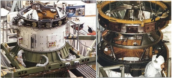 Left: Atlantis’ STS-71-specification APDA unit and the white “vestibule” or docking base sitting atop the Orbiter Docking System’s external airlock. Seen here before the insulation and micrometeoroid protection blankets were applied. Right: The STS-71-specification docking unit undergoing final fit checks with an APAS tester at KSC. (credit: AWST Jul. 3 1995, AWST Apr. 3 1995) |
In an effort to ensure dual redundancy in all critical components of the docking system, explosive bolts were fitted on all 24 structural hooks in Atlantis’ APDA. If even that failed, the astronauts were to manually remove the 96 bolts holding the docking base to the ODS’ airlock.[8]
After tests at Energia’s Konus stand showed that the reliability of docking decreased substantially at the lower approach velocity planned for shuttle, a decision was made to fire the orbiter’s RCS thrusters after the soft capture mechanism made contact to encourage it to latch.
The four electrical interface connectors which allow two spacecraft equipped with APAS to transmit power and data without the need to manually run cables through the docking passage were removed from the perimeter of the hard docking collar as they were deemed unnecessary—Atlantis’ docking would be purely mechanical.
 A view at Atlantis’ APDA during STS-71. Note the extended soft capture mechanism of the APDA and the clean perimeter of the docking collar without the interface connectors. (credit: NASA) |
The APDA was now an autonomous system, controlled from a remote panel on the Shuttle’s flight deck, while the control electronics themselves were located under the floor of the ODS’ external airlock. Continuing with NASA jargon, the APDA (APAS assembly) and its avionics formed the Androgynous Peripheral Docking System (APDS).[19]
The APDA used on STS-71 in June 1995 had the Energia part number 008–05 (serial №005) and NASA/Rockwell designator -3001. [15, 20, 21]
STS-74 and the Mir Docking Module
By the time the follow-up to STS-71 was in the planning stages, the Shuttle-Mir program was expanded with more docking missions and, in 1996, expanded once more to a total of nine. To allow the shuttle to dock to Mir without the need to re-dock Kristall for every mission, the participating nations decided to build the Mir Docking Module, scheduled to launch on STS-74, Atlantis’ second flight to Mir. [22, 23]
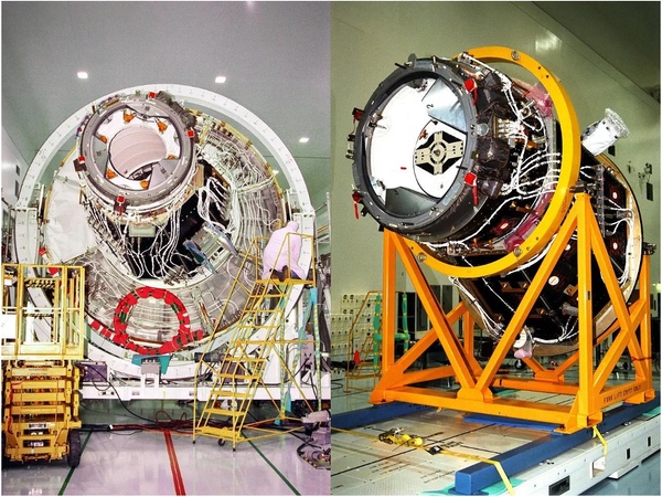
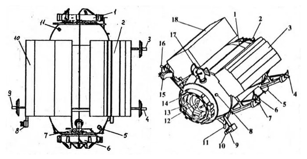 Drawings of the Mir Docking Module. (credit: Novosti Kosmonavtiki №23 1995) |
The Mir Docking Module was a rounded cylinder with APAS units at either end. The two docking ports were of almost identical, androgynous specification, but APAS №2 was always used as the passive target port, while APAS №1 was the active unit. APAS №1’s hatch was fitted with a porthole; on APAS №2 that space was occupied by a docking target, and the №2 unit was configured without the rubber gaskets on the hard docking collar.
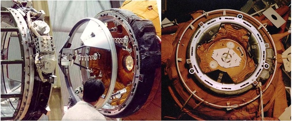 Left: The Mir Docking Module undergoing pre-flight fit checks of the №1 APAS assembly with an APDA. Note the porthole and two red sealing gaskets on the №1 APAS and the extra hydraulic connectors on the APAS on the left. Right: The MDM’s №2 APAS as seen by the crew of STS-81. (credit: SICSA/University of Houston, NASA) |
After reaching orbit, Atlantis’ crew used the Canadarm to position the MDM’s APAS №2 over the orbiter’s docking port and used the orbiter’s RCS thrusters to provide the impulse needed for the soft capture latches of the APDA on Atlantis to catch. After engaging the hard docking latches, the Atlantis-MDM combination then used the latter’s active APAS №1 to dock to Kristall. After the mission was completed, Atlantis undocked from the Mir Docking Module, leaving it attached to the station ready for seven more visits of the shuttle.
| Speaking of Pressurized Mating Adapters, these weirdly shaped docking tunnels use two very different APAS assemblies. |
To perform this maneuver, however, Atlantis’ crew needed to be able to control APAS №1 on the Mir Docking Module from the orbiter, which was impossible with the purely mechanical interface used on STS-71. With the STS-74 mission scheduled just four months after STS-71, a new version of the APDA was developed and built into the second APDA unit.
The STS-74 docking assembly picked up where STS-74’s -3001 unit left off with the same modifications to adapt the APAS to the shuttle’s electrical and control system, but this time the four electrical interface connectors from APAS-89 were retained; two with 184 contacts delivering 1.4 kilowatts of electrical power and two with 151 contacts for control and data channels.
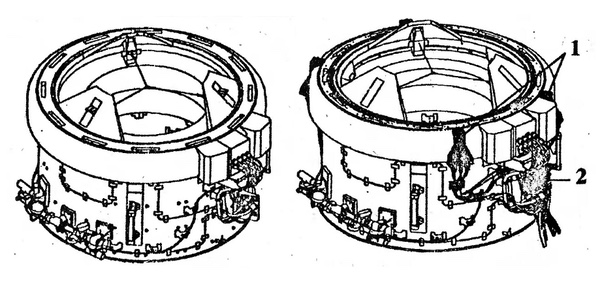 Comparison of the STS-71 (left) and STS-74 (right) APDA configurations, with 1 denoting the electrical interface connectors and 2 denoting the switching system box. (credit: Novosti Kosmonavtiki №23 1995) |
To allow control of both the orbiter-mounted docking assembly and APAS №1 on the MDM from the same control panel in the orbiter, a switching system was mounted on the outside of the hard docking collar. The APDS Switching System was an electromechanical device that physically disconnected the wiring used to control and monitor the orbiter’s docking assembly and rerouted it to the APAS №1 assembly on the MDM through the four electrical interface connectors on the APDA, letting APAS №1 behave like the orbiter’s only docking port. [24]
This specific APDA unit was used on six Shuttle-Mir missions, STS-74 (November 1995) through STS-86 (September 1997), all flown by Atlantis, after which it was retired.
 Atlantis docks to Kristall using the Mir Docking Module as an extension of its own docking port with the help of the APDS Switching System. (credit: NASA) |
Both APAS assemblies on the Mir Docking Module had the Energia part number 008–06. Atlantis’ APDA for STS-74 had the same 008–05 Energia part number as STS-71's -3001 unit, but obviously a different serial number—which, like its NASA/Rockwell designator, I was not able to find. [15, 25]
STS-89 and the birth of the ISS
After STS-86, Atlantis was sent for its second Orbiter Maintenance Down Period (OMDP-2) to Rockwell’s Palmdale facility to prepare for its role in ISS assembly, leaving the last two Shuttle-Mir flights to Discovery. [26]
Meanwhile, Endeavour’s next mission was to be the first American ISS assembly flight, mission 2A (STS-88), which carried Node 1 and Pressurized Mating Adapters 1 and 2. Just like with Atlantis on STS-74, once in orbit, Endeavour’s crew would retrieve Node 1 from the payload bay using the manipulator arm and berth it to the orbiter’s APDA. The combination would then berth itself to the Zarya FGB through PMA-1’s active APAS port. As this was to be the only ISS flight that needed the APDS Switching System to gain control of a different docking assembly than the orbiter’s own, the original APDA unit used on STS-71 was brought back from retirement and upgraded to match the STS-74 specification; its NASA designator was hence changed from -3001 to -3002. [27, 28]
In May 1997, program managers announced that Endeavour, which had just been fitted with the interim Orbiter Docking System and the retrofitted -3002 APDA, would fly the penultimate Shuttle-Mir mission, STS-89, instead of Discovery. [29] After STS-89 in January 1998, Endeavour successfully completed the STS-88 mission in December 1998, delivering Node 1 and PMA’s 1 and 2, after which it was refitted with a newer docking assembly and APDA-3002 was retired from service. The -3002 unit retained the Energia product code 008–05 (serial №005) from its days as unit -3001. [20]
STS-88 and non-androgynous androgyny
Speaking of Pressurized Mating Adapters, these weirdly shaped docking tunnels use two very different APAS assemblies.
PMA-1, used to connect Node 1 and Zarya, uses an active version of the STS-74-style APDA, because it requires the switching system to extend the orbiter’s controls to connect to the passive port. Due to its location at the center of the space station, permanently joining the Russian and US orbital segments, PMA-1’s APDA was designed to be latched with all 24 structural hooks: the 12 active hooks engaged from the PMA side and 12 passive hooks latched by the active hooks on Zarya. For the same reason, the APDA was not fitted with explosive bolts on any of the structural hooks. [27]
 PMA-1 with its active APDA (left) and PMA-2 with its passive APDA (right). The passive assembly’s rough alignment petals are bolted in place and do not feature soft capture latches. Note that the hard docking latches on both APDAs are obscured by protective covers. (credit: NASA) |
The docking ports on PMA-2 and -3 are of the rare fully passive configuration. The entire soft capture mechanism has been removed, leaving only the three rough alignment petals hard-bolted to the hard docking collar and the soft capture strikers for the docking assembly of the visiting spacecraft to latch onto. Like the operationally passive APAS ports on Kristall, these docking assemblies do not have the rubber sealing gaskets and their hard docking latches can be actuated from the station side to achieve a hermetic connection in case the latches of the visiting vehicle fail. They were not fitted with explosive bolts on any of the structural hooks. A similar, fully passive assembly is installed at the forward end of the Zarya FGB for docking with PMA-1.
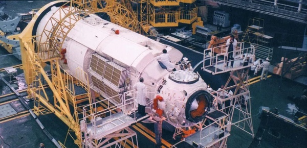 Zarya in the processing area in Baikonur’s MIK 254. (credit: msk.kprf.ru) |
PMA-1’s docking unit received the -7001 NASA designator, but, being almost identical to the Mir APDAs, bore a familiar Energia product code, 008–05 (serial №004). The PMA-2 and -3 APDAs received the -8001 NASA designator and 008–08 Energia product codes. [30]
Sidebar: ICM and hybrids
An interesting curiosity are the two APDAs designed for use with the unflown Interim Control Module; NASA’s contingency plan if the Russian Service Module fails to reach the station before the electrical power and fuel on the FGB run out.
The ICM was based on the leftover Shuttle/Titan Launch Dispenser hardware and would be launched on the shuttle. Once in space, just like Node 1 and the Mir Docking Module before it, the ICM would be berthed to the shuttle’s APDA through the passive aft APDA. The interesting bit is that at the forward end, the ICM had an active APDA, but it would dock to the SSVP-M aft port of Zarya.
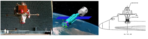 ICM during testing (left), berthed to the orbiter (center) and docked to Zarya and Node 1 (right). (credit: NRL, JSC-26938, NASA) |
SSVP-M is also known as the hybrid docking system; it uses the hard docking collar from APAS and the soft capture mechanism from the standard “probe and cone” SSVP-G design. The hybrid system allows the soft capture mechanism to be swapped between the two standards in flight, allowing the active “probe” to make way for the passive APAS interface.
In Zarya’s case, if the ICM needed to be docked to its aft docking port, the station’s crew would have replaced the active “probe” with the APAS alignment petals and an “FGB Pressure Dome” to accept the APDA. [31, 32]
While the ICM was not needed in the end, during pre-flight testing Zarya could be spotted with both soft capture mechanisms installed at the same time, though it launched with just the SSVP soft mechanism.
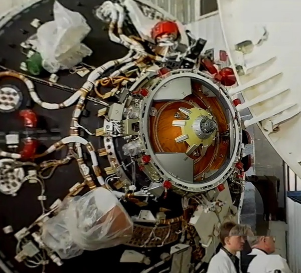 Image: “FGB Zarya” on YouTube |
The ICM’s APDAs would have reused the Mir-era APDS Switching System hardware to facilitate the berthing to Zarya, but the docking assemblies themselves were newly built. Unlike on PMA-2 and -3, the passive APDA on the ICM featured fully passive hard docking latches. The APDA on the orbiter that delivered the ICM would have been the -3002 unit, implying that that orbiter was Endeavour.
The Interim Control Module’s active APDA bore the NASA designator -7002 and Energia product code 008-11. The passive APDA bore the NASA designator -8002 and Energia product code 008–12. [33]
STS-91 and how everyone is so soft these days
After reducing the approach speed for Shuttle-Mir dockings using the APAS system to limit the loads on the vehicles, workarounds such as firing the RCS thrusters at contact with the soft capture mechanism became a requirement to ensure reliable docking. With the future International Space Station projected to mass more than three times as much as Mir, docking a shuttle to the orbital complex would subject the orbiter to unacceptably large loads and disrupt the microgravity environment aboard the station until the oscillations died down—during Shuttle-Mir, this process took as long as eight minutes from soft capture. During the winter of 1993–94, at the request of Rockwell, Energia started development of a new, soft APAS. [34, 9]
| With the future International Space Station projected to mass more than three times as much as Mir, docking a shuttle to the orbital complex would subject the orbiter to unacceptably large loads. |
The soft APAS concept led to the system’s most mechanically comprehensive overhaul since its inception as APAS-89. To reduce the required approach speed and dampen the oscillations after soft capture, the system gained an additional actuator and gearbox, and the ball screw dampers were upgraded with new units developed by NPO “Dzerzhinets”. The Americanized avionics developed for Shuttle-Mir were retained. On the Rockwell-built side, no longer limited by clearance with Kristall, the Orbiter Docking System was moved right against the forward bulkhead of the payload bay and became a permanent addition to the orbiters after installation.
The revised system became the basis for all active APDAs used on Shuttle flights to the International Space Station (with the exception of the aforementioned STS-88 unit) and received the NASA designator -6001. [35, 27]
During its second Orbiter Maintenance Down Period (OMDP-2) between September 1995 and June 1996, Discovery became the first orbiter to be fitted with the definitive ODS and the ISS-specification -6001 APDA. The system made its debut during the last Shuttle-Mir docking mission, STS-91 in June 1998 and flew the first ISS docking mission, STS-92 (assembly flight 3A) in October 2000, both aboard Discovery. [36]
 Discovery became the first orbiter to be fitted with the permanent ODS and the ISS-specification APDA. Note the change in the color of the insulation blankets inside the APDA from orange on the Mir specification to white on the “soft” ISS specification. (credit: NASA) |
By September 1998, during Atlantis’s OMDP-2 the interim ODS was replaced with the definitive ISS specification and the new -6001 APDA was installed. The last orbiter to join the soft APAS fleet was Endeavour, refitted with the new APDA before STS-97 (assembly flight 4A) in November 2000. All Shuttle missions to the ISS after STS-88 used the -6001 series APDAs. All -6001 units were fitted with the full set of 24 explosive bolts for both active and passive structural hooks. The -6001 unit received the Energia product code 008–09. [37]
APAS-95
Where is the famous APAS-95 in all of this? Well, here’s the thing. There really isn’t such a thing as APAS-95.
APAS assemblies used in the US were given the APDA moniker and a four-digit product code (e.g. -3002) to tell the specifications apart, but “APAS-95” simply wasn’t in use, at least in the ISS program’s early years. Russian publications and even the system’s chief designer Vladimir Syromyatnikov refer to it as “APAS-89-type” or simply “APAS”. Most damningly, Energia’s own product codes show that while each configuration was given a new code, they all belong to the same ZZU.6201.008 series, starting with the -01 type on Kristall—which is definitely APAS-89—and ending at the unbuilt -11 and -12 types for the Interim Control Module, whose avionics, electrical system and soft capture mechanism are distinctly different from the ones used on Kristall. Yet, they remain fully mechanically compatible.
I’ve seen the argument that APAS-95 could represent the “soft” APAS designed for the ISS and used only with non-androgynous target ports: the shuttle always assumed the active role and docked to a fully passive PMA that did not even have a soft capture mechanism. In that case, why name it APAS-95, when it was conceived in 1993–94, flown to Mir first (in 1998), and only flown to the ISS in 2000?
The best I can come up with is that any Americanized APAS assembly, i.e. one adapted to the Shuttle’s electrical system, constitutes APAS-95. It made its first public appearance and was first flown in 1995. What an anticlimax!
References
- V.S. Syromyatnikov, “100 Stories About Dockings and Other Adventures in Space and on Earth” (“100 рассказов о стыковке и о других приключениях в космосе и на Земле”), Moscow, Logos, 2008
- K. Lantratov, I. Lisov, “ODS Docking System”, Novosti Kosmonavtiki, №13, 1995, p. 17
- I. Afanasyev, D. Vorontsov, “The failed ‘Zarya’”, Novosti Kosmonavtiki, №8, 2014, p. 25
- Syromyatnikov, pp. 217–220, 222
- K. Lantratov, I. Lisov, “APAS operation during docking and undocking”, Novosti Kosmonavtiki, №13, 1995, p. 18
- “Procurement Specificationfor the Androgynous Peripheral Docking System for the ISS Missions: Revision C”, JSC-26938, Johnson Space Center, July 17, 1998
- J. McKenna, “Mir Docking Device Readied for Rendezvous”, Aviation Week & Space Technology, Sept. 19, 1994
- “Shuttle-Mir Plans Hit Technical Snag”, Aviation Week & Space Technology, Jul 4, 1994
- J. R. Asker, “Shuttle Docking System Performs Many Tasks,” Aviation Week & Space Technology, Jul. 3, 1995
- Syromyatnikov, p. 223
- I.A. Mavinin, S.Kh. Shamsutdinov, O. V. Khdanovich (eds.), “Flight plans for Buran-2”, Novosti Kosmonavtiki, №1, 1991, p. 2
- Syromyatnikov, pp. 323–324
- I.A. Marinin (ed.), “News from the CPC”, Novosti Kosmonavtiki, №1, 1993, p. 14
- I. Lisov, “Backup options”, Novosti Kosmonavtiki, №13, 1995, p. 19
- K. Lantratov, “316GK docking module”, Novosti Kosmonavtiki, №23, 1995, p. 44
- Product code is ZZU.6201.008–01; photos of the module in orbit show a docking collar marked with ZZU.6201.008–03.
- Syromyatnikov, p. 107
- V.D. Blagov et al., “Joint Shuttle-Mir Operations”, p. 107
- Syromyatnikov, pp. 334–335, 478
- JSC-26938, fig. 2a
- The STS-71 APDA has Energia code ZZU.6201.008–05–005, NASA code MC621–0087–3001.
- Syromyatnikov, p. 469
- “316GK docking module”, p. 42
- “316GK docking module”, p. 45
- The full Energia product code is ZZU.6201.008–06.
- J. Deming, P. Slovinac, “Space Transportation System”, Historic American Engineering Record (HAER) No. TX-116, Lyndon B. Johnson Space Center, pp. 72, 107
- Syromyatnikov, p. 38
- Blagov, p.53
- HAER TX-116, p. 77
- PMA-1’s APDA has Energia code ZZU.6201.008–05–004, NASA code MC621–0087–7001. PMA-2 and 3’s APDAs have Energia code ZZU.6201.008–08, NASA code MC621–0087–8001.
- V. Sorokin, “International Space Station: Russia. News from the Russian segment”, Novosti Kosmonavtiki, №24, 1997, p. 49
- Yu. Zhuravin, “What is the FGB?”, Novosti Kosmonavtiki, №1, 1999, p. 7
- The ICM’s active APDA has Energia code ZZU.6201.008–11, NASA code MC621–0087–7002, the passive APDA has Energia code ZZU.6201.008–12, NASA code MC621–0087–8002. JSC-26938, p. 588
- Syromyatnikov, p. 357
- Ibid., p. 358
- HAER TX-116, p. 115
- The ISS-specification “soft” APDAs have Energia code ZZU.6201.008–09, NASA code MC621–0087–6001.
Note: we are now moderating comments. There will be a delay in posting comments and no guarantee that all submitted comments will be posted.