

Powering a Moon base through the lunar nightby Joseph Barrett Bland, Michael Abramson, and Roger Arnold
|
| The group decided to examine the possibility of powering a Moon base through the lunar night with a laser either at L1 or in lunar orbit. |
Mass doesn’t necessarily have to be lifted directly from Earth to its final destination. For some SL5S calculations, it is assumed that the propellant and electric propulsion (EP) drive used to move a mass from LEO to either lunar orbit or EML1 will equal 30 percent of the transported mass. An EP system can also be used for orbital station keeping, which can be broadly defined as maintaining an object in space in a preferred position or orbit
The SL5S analysis examined energy storage by flywheel, electric battery, chemical, and thermal battery systems. It was concluded that lithium-sulfur (Li-S) batteries presently appeared to have the best specific energy (measured in kilowatt-hours per kilogram), but that other systems would benefit greatly from in situ resource utilization (ISRU) and would become competitive fairly rapidly once manufacturing on the lunar surface began. A specific energy of 0.5 kilowatt-hours per kilogram for Li-S has been used in the SL5S analysis as the basis for energy storage mass calculations for all systems.
As originally suggested by SL5S member Roger Arnold, aggressive collimation of a laser beam with a Fresnel optical lens could be used to dramatically reduce the diameter of a laser beam over a long distance since, for a given light wavelength and distance to target, spot diameter is inversely proportional to aperture diameter. Aggressive laser collimating may be especially practical in a weightless, weather-less environment. Because objects in space are weightlessness, and because space has no atmosphere, a space-based Fresnel laser collimating lens might only be a few mils thick. In this analysis, the mass of a Fresnel lens, including the mounting framework, is assumed to be 0.25 kilograms per square meter, with most of that mass assumed to be in the mounting framework.
Two different different approaches to powering a laser were examined. One uses electricity to power the laser. The system utilizes photovoltaic cells, although the electricity can also be created by a heat engine driven by concentrated solar energy. Another type of system is possible using solar-pumped lasers. In such a system, the solar insolation is concentrated directly on the laser, bypassing the electrical conversion system. Efficiencies for the two systems are expected to eventually be about the same, but the solar-pumped one appears to have a higher specific power even at present efficiencies.
A satellite that is not in sun-synchronous lunar orbit will move regularly into the Moon’s shadow. Adding an energy storage system permits an orbiting laser system to continue beaming energy even when this occurs. This energy storage system can also be used with a sun-synchronous satellite to store energy until the laser system can regain direct contact with the lunar base. Finally, by leaving parts of the energy storage system in orbit rather than moving it to the lunar surface, the overall project mass can be reduced, since rocket motors, fuel, and so on can be scaled back.
A deflecting system, as the term implies, permits a laser beam to be deflected. In certain circumstances, such a system in lunar orbit may permit nearly uninterrupted laser beaming from an orbiting solar-powered laser system to a given location, thus obviating the need for energy storage either in orbit or on the lunar surface.
| The OLO appears to be able to operate in much closer proximity to the Lagrangian point with which it is associated than a halo orbit. This is important for beaming energy to the lunar surface from EML1 or EML2. |
A deflecting can also find use in other ways. It is possible to envisage a series of non-orbiting deflection modules placed directly on the lunar surface to transfer beamed energy to other locations. Finally, a surface-based solar powered laser system at the lunar poles may beam solar-powered laser energy to an orbiting deflecting system, distributing lunar pole-generated laser energy to other locations on the Moon (see Lunar Polar Multi-array System below).
In January of 2015, the SL5S analysis was essentially complete when the organization discovered a presentation titled “NASA JSC Lunar Surface Concept Study.” Since January, SL5S conducted an extensive rewrite of its analysis to actively compare the earlier analysis with the 2009 NASA study.
The preferred system recommended in the 2009 NASA study was a photovolatic solar array-powered cryogenic storage regenerating fuel cell system. NASA calculated that a five-kilowatt continuous delivery system would store 2,000 kilowatt-hours with a system energy density of 1.15 kilowatt-hours per kilogram. The study’s alternate preferred system was a fixed orbit laser system, with a 16.1-hour orbit period that required a surface receiver installation with 525 kilowatt-hours of energy storage. The laser was powered and fired when it was both in direct sunlight and in direct line-of-sight with the Moon base.
One concept that was not explored in the 2009 NASA study is the use of several separate solar collectors situated on high lunar mountain peaks, or so-called “peaks of eternal light,” each connected directly to the base via electric cables, lasers, or reflected solar beams. This concept was suggested by SL5S member Michael Abramson in early February of this year. Such a system would approach a continuously-powered polar Moon base. Periods of darkness as long as 36 hours may still be likely, requiring additional energy storage capacity, estimated at 540 kilowatt-hours.
Yet another approach to continuously powering a Moon base was looked at and rejected by NASA as impractical. That approach involved parking a solar-powered laser system at the Earth-Moon L1 or L2 points. However, in making its determination, NASA did not consider the possibility of using aggressive laser collimating.
For any two bodies in space rotating about a common center, there are five points of special interest called Lagrange points. For the Earth-Moon system, they’re called EML1, EML2, and so on.
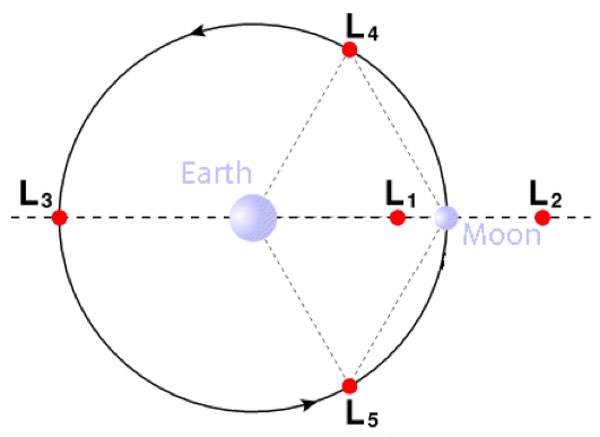 |
In the case of EML1, this point is between the Earth and the Moon and along a line between their centers of gravity. In the case of EML2, this point is along the same line but beyond the far side of the Moon. The Lagrange points mark positions where the combined gravitational pull of the two bodies precisely matches the centripetal force required for the points to orbit with those bodies. For example, an object placed at EML1 orbits at the same rate as the Moon even though it is much closer to the Earth.
Lagrange points L1, L2 and L3 are said to be unstable. That is, it requires a force to maintain an object’s position in their vicinity. One type of orbit, called a “halo orbit,” while also unstable, is much more stable than an object placed exactly at one of these Lagrange points. A halo orbit is a three-dimensional somewhat circular orbit approximately perpendicular to the center line connecting the Earth and the Moon at the approximate location of the Lagrange point along that line.
Presently, station keeping in the vicinity of EML1 or EML2 is usually accomplished by a three-dimensional halo orbit. An alternative approach known as the oscillating Lagrange point orbit (OLO), is largely a two-dimensional orbit in the two-body orbital plane. The figure below generally illustrates the theorized course of an OLO over the roughly four weeks of a lunar rotation, as mapped along the approximately 6,400-kilometer line of travel of L1 relative to the Moon between perigee and apogee.
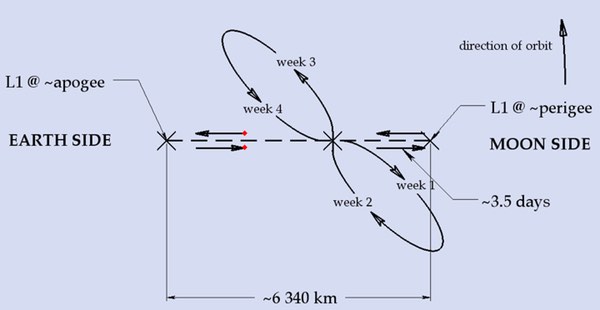 |
Looked at from above or below the Earth-Moon plane, the OLO approximates a figure eight, orbiting alternatively along the lobe on one side of the line connecting the center of the Earth and the center of the Moon and then along the lobe on the other side of that line. Note that the center line is relative to Earth and Moon and is described by the elliptical movement of the Moon as it orbits around the Earth/Moon barycenter. SL5S member Roger Arnold, originator of this concept, put it this way:
“The metastable neutral point that the station should track is not the L1 point, wherever it happens to be at any given moment. Rather, it’s a point in the 6D phase space for the system (x, x-dot, y, y-dot, and z, z-dot). I.e., both position and velocity vectors must be right. When they are, the station describes an oscillating “orbit” that passes through the L1 point twice per month. Once the station achieves the neutral point, I believe the only station keeping that’s needed is to correct for drift due to measurement errors and unaccounted solar radiation pressure. The neutral point that the station follows will oscillate with the L1 point, but with lesser amplitude and lagging in phase. The proper analogy is to balancing a weight atop a pole whose base is oscillating back and forth. The weight does not precisely track the base and remain positioned exactly above it.”
| In light of the dramatic nature of those findings, it is felt that the systems in question merit a far more in-depth analysis than the S5LS is capable of delivering. |
The OLO appears to be able to operate in much closer proximity to the Lagrangian point with which it is associated than a halo orbit. This is important for beaming energy to the lunar surface from EML1 or EML2. Work is presently being carried out by the SL5S to roughly estimate the extents of a typical OLO at EML1.
In certain circumstances, a solar sail arrangement can be used to enhance or even replace an electric propulsion system for OLO station keeping purposes at EML1/EML2. This system has an advantage because of its ability to modify a spacecraft’s position without using fuel. A related idea is the use of reels to pull in or let out either solar sails or “gravity anchors” relative to a space-based platform. This constitutes what might be called the concept of a “gravity winch.” A gravity winch is basically a reeled tether that’s dropped down gravity wells from a “neutral” gravity point, such as a Lagrange point. In the case of a platform at EML1, a tether can be dropped from the platform down the gravity wells of both the Moon and Earth. Shifting the gravity anchors from one side of the platform to the other allows the EML1 platform to “balance” between the two gravity wells, similar to the way a pole helps a tightrope walker balance. This technique may also be useful for putting in place a “lunar elevator” extending from EML1 to the lunar surface.
The table below collates the results of our analysis. The Cryogenic-storage Regenerating Fuel Cell (CRFC) and Fixed Orbit Laser System (FOLS) systems are included for reference purposes only. This presumes that any advances in battery technology will be applied across the board to all systems. To aid in comparisons, a CRFC-type system using Li-S energy storage is included as the Lunar Non-polar Surface Mounted System (LNSMS). Also, a FOLS-type system using Li-S energy storage and aggressive laser collimating is included as the Lunar Orbiting Photovoltaic-powered Laser System (LOPVLS).
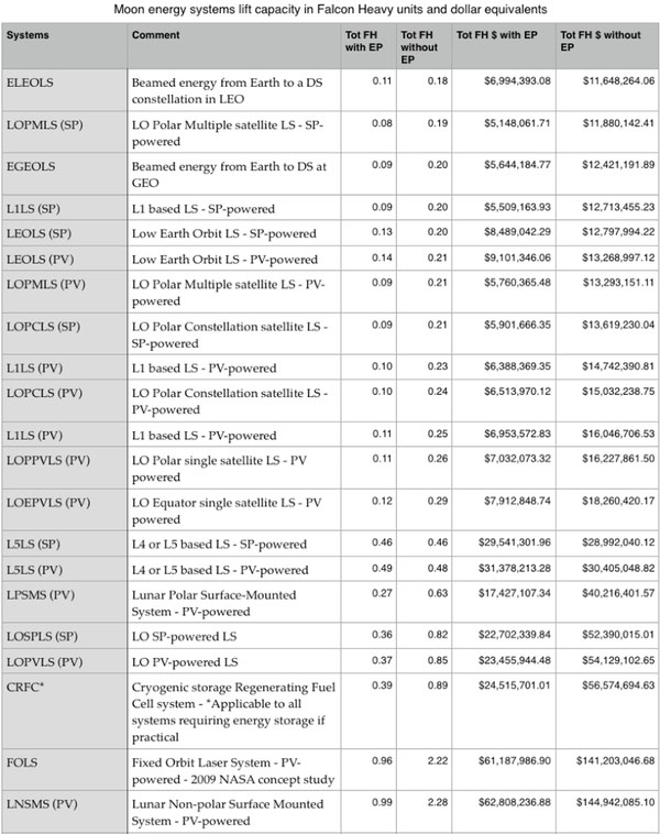 |
In the table, the 15-kilowatt continuous systems are shown ranked from low cost to high cost by the column “Tot FH $ without EP” (Total Falcon Heavy cost without electric propulsion). It is assumed that, for an initial Moon base, electric propulsion will not be used to deliver the payloads to their ultimate destinations. FH dollars are calculated based on a price of $1,200 per kilogram in accordance with the statement by SpaceX CEO Elon Musk that, “Ultimately, I believe $500 per pound or less is very achievable.” It’s important to note that FH dollars do not include any costs associated with developing the various systems shown in the table.
The findings of the SL5S analysis are very much first order approximations. In addition, the analysis is still a work in progress. However, in light of the dramatic nature of those findings, it is felt that the systems in question merit a far more in-depth analysis than the S5LS is capable of delivering. It is hoped that this article will inspire the undertaking of such an in-depth analysis by NASA or some other interested party.
